Overview
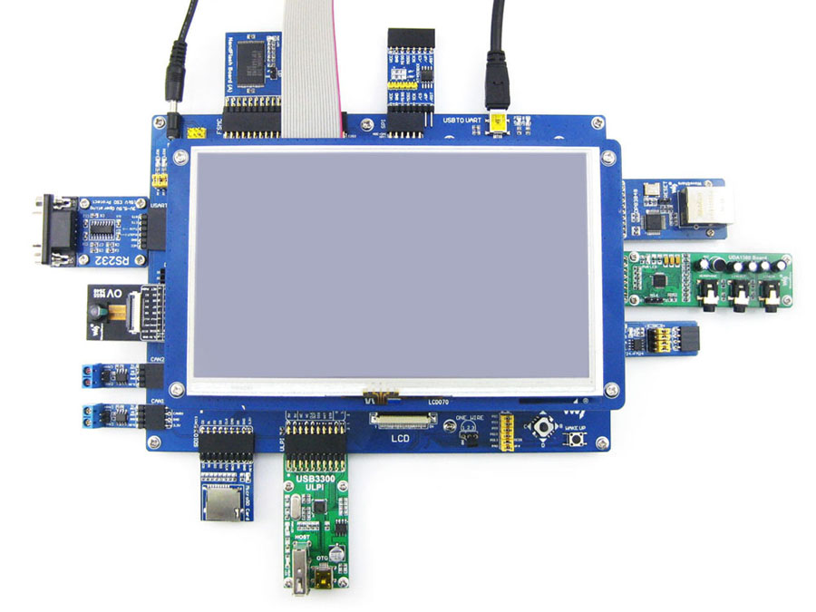
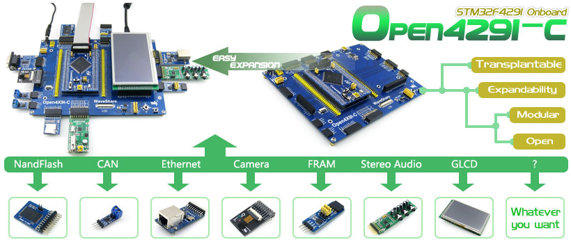
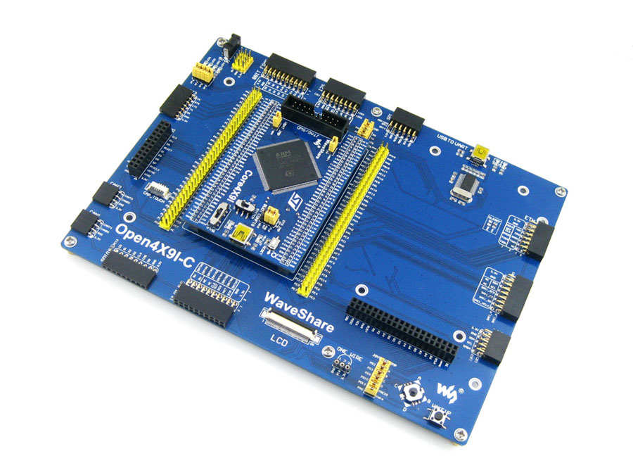
Open429I-C はSTM32F429IGT6 microcontroller向けの STM32 development board で、マザボードとMCU core boardCore429Iで出来ています。.
Open429I-Cは STM32 シリーズのマイクロコントローラーの開発に最適です。.
---------------------------------------
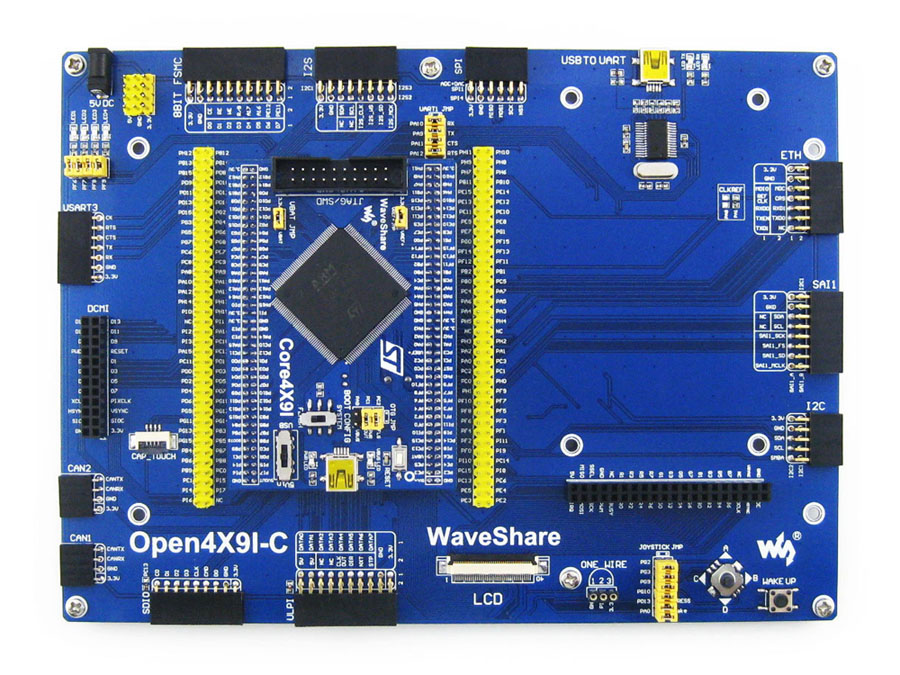
What's on the mother board
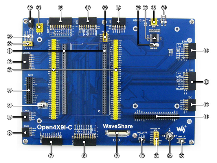
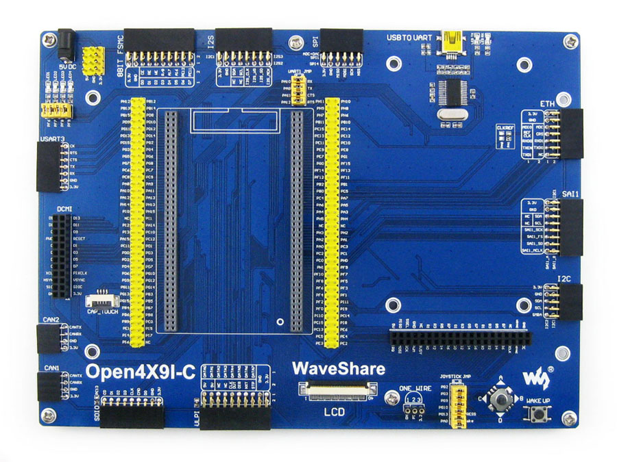
1. MCU core board connector: for easily connecting the Core429I
2. USART3 interface: easily connects to RS232, RS485, USB TO 232, etc.
3. DCMI interface: for connecting camera
4. Capacitive touch panel interface: for connecting capacitive touch panel
5. CAN2 interface: for connecting CAN modules
6. CAN1 interface: for connecting CAN modules
7. SDIO interface: for connecting Micro SD module, features much faster access speed rather than SPI
8. ULPI interface: for connecting high-speed USB peripheral (the STM32F429I integrates USB HS controller without any PHY device)
9. LCD interface 1: for connecting 7inch LCD
10. ONE-WIRE interface: easily connects to ONE-WIRE devices (TO-92 package), such as temperature sensor (DS18B20), electronic registration number (DS2401), etc.
11. LCD interface 2: for connecting 4.3inch LCD
12. I2C2/I2C3 interface: easily connects to I2C peripherals such as I/O expander (PCF8574), EEPROM (AT24Cxx), etc.
13. SAI1 interface: for connecting audio modules like UDA1380 module
14. Ethernet interface: for connecting Ethernet modules
15. USB connector: USB to UART via the onboard convertor PL2303
16. SPI1/SPI2 interfaces:
-easily connects to SPI peripherals such as DataFlash (AT45DBxx), SD card, MP3 module, etc.
-easily connects to AD/DA modules (SPI1 features AD/DA alternative function)
17. I2S2/I2S3/I2C1 interface: easily connects to I2S peripherals such as audio module, etc.
18. 8-bit FMC interface: easily connects to peripherals such as NandFlash
19. 5V DC jack
20. 5V/3.3V power input/output: usually used as power output, also common-grounding with other user board
21. MCU pins connector: all the MCU I/O ports are accessible on expansion connectors for further expansion
22. PL2303: USB to UART convertor
23. LEDs: convenient for indicating I/O status and/or program running state
24. PL2303 TX-LED / RX-LED
25. 12MHz crystal: for PL2303
26. Joystick: five positions
27. WAKE UP button: used as regular button, and/or wake up the STM32 MCU from sleep
28. USB to UART jumper
29. LED jumper
-short the jumper to connect to default I/Os used in example code
-open the jumper to connect to custom I/Os via jumper wires
30. Button/Joystick jumper
-short the jumper to connect to default I/Os used in example code
-open the jumper to connect to custom I/Os via jumper wires
What's on the Core429I
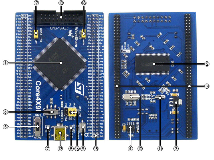
1. STM32F429IGT6: the high performance STM32 MCU which features:
-Core: Cortex-M4 32-bit RISC
-Feature: single-cycle DSP instructions
-Operating Frequency: 180MHz, 225 DMIPS/1.25 DMIPS/MHz
-Operating Voltage: 1.8V-3.6V
-Package: LQFP176
-Memories: 1024kB Flash, 256+4kB SRAM
-MCU communication Interfaces:
=6 x SPI, 4 x USART, 4 x UART, 2 x I2S, 1 x SAI, 3 x I2C
=1 x FMC, 1 x SDIO, 2 x CAN
=1 x LCD-TFT
=1 x USB 2.0 HS/FS controller (with dedicated DMA)
=1 x USB HS ULPI (external PHY required)
=1 x 10/100 Ethernet MAC
=1 x 8 to 14-bit camera interface
-AD & DA converters: 3 x AD (12-bit, 1μs, shares 24 channels); 2 x DA (12-bit)
-Debugging/Programming: supports JTAG/SWD interfaces, supports IAP
2. IS42S16400J: SDRAM 1 Meg Bits x 16 Bits x 4 Banks (64-MBIT)
3. AMS1117-3.3: 3.3V voltage regulator
4. MIC2075: onboard USB power management device
5. Power supply switch, powered from 5Vin or USB connection
6. Boot mode selection, for configuring BOOT0 pin
7. Power indicator
8. VBUS LED
9. Reset button
10. 8M crystal
11. 32.768K crystal, for internal RTC with calibration
12. JTAG/SWD interface: for debugging/programming
13. USB connector, supports Device and/or Host
14. MCU pins expander, VCC, GND and all the I/O pins are accessible on expansion connectors for further expansion
15. 5Vin pinheader, 5V power supply is required when using USB HOST/OTG
16. USB OTG/HOST jumper
-short the jumper when using USB OTG/HOST
-open the jumper to disconnect from related I/O port
17. VBAT selection jumper
-short the jumper to use system power supply
-open the jumper to connect the VBAT to external power, such as battery
18. VREF selection jumper
-short the jumper to connect VREF+ to VCC
-open the jumper to connect VREF+ to other custom pin via jumper wire


 (赤外線LED別)")