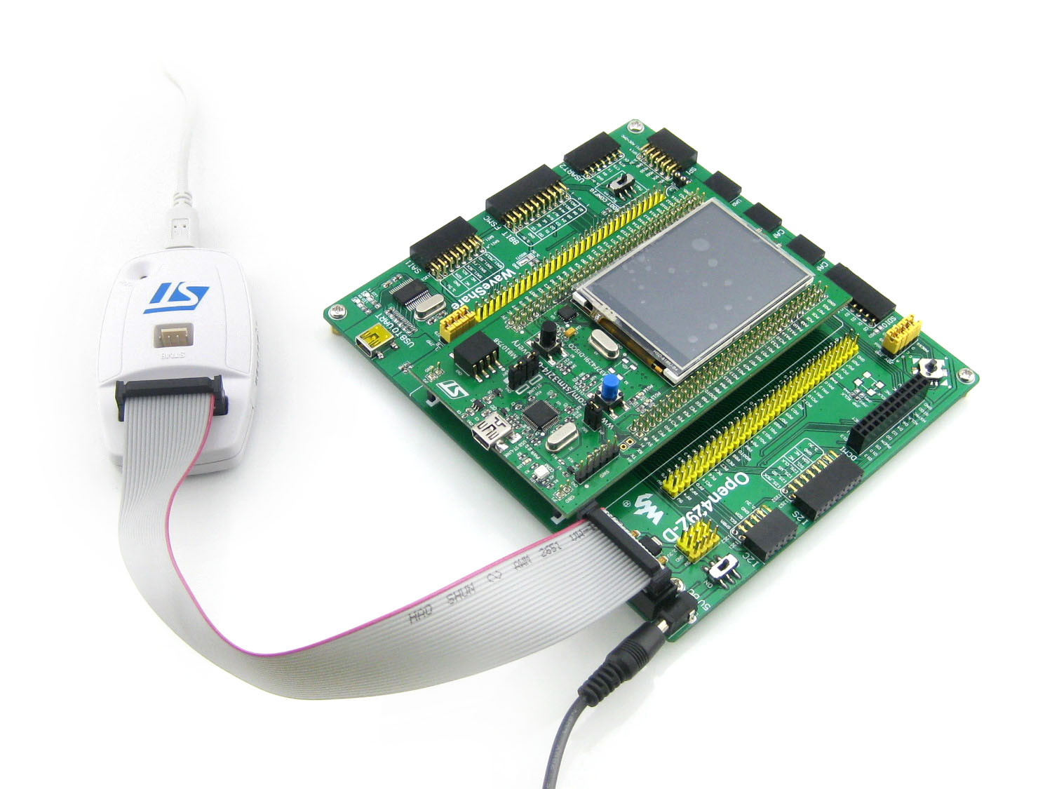
What's on the mother board
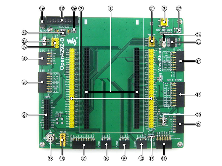
1. STM32F429I-DISCO socket: for easily connecting the STM32F429I-DISCO
2. MCU pins connector: all the MCU I/O ports are accessible on expansion connectors for further expansion
3. USB connector: USB to UART via the onboard convertor PL2303
4. I2C1/I2C2 interface: easily connects to I2C peripherals such as I/O expander (PCF8574), FRAM (FM24CLxx), etc.
5. I2S2/I2S3/I2C1 interface: easily connects to I2S peripherals such as audio module, etc.
6. DCMI interface: for connecting camera
7. SDIO interface: for connecting Micro SD module, features much faster access speed rather than SPI
8. CAN1 interface: communicates with accessory boards which feature the CAN device conveniently
9. CAN2 interface: communicates with accessory boards which feature the CAN device conveniently
10. UART3 interface: easily connects to RS232, RS485, USB TO 232, etc.
11. SPI1/SPI4 + AD/DA interfaces:
-easily connects to SPI peripherals such as DataFlash (AT45DBxx), SD card, MP3 module, etc.
-easily connects to AD/DA modules (SPI1 features AD/DA alternative function)
12. UART2 interface: easily connects to RS232, RS485, USB TO 232, etc.
13. 8-bit FMC interface: easily connects to peripherals such as NandFlash
14. SAI1 interface: for connecting audio modules like UDA1380 module
15. ONE-WIRE interface: easily connects to ONE-WIRE devices (TO-92 package), such as temperature sensor (DS18B20),
electronic registration number (DS2401), etc.
16. 5V DC jack
17. 5V/3.3V power input/output: usually used as power output, also common-grounding with other user board
18. JTAG/SWD interface: for debugging/programming
19. Joystick jumper
-short the jumper to connect the joystick to default I/Os used in example code
-open the jumper to connect the joystick to custom I/Os via jumper wires
20. Boot mode switch: for configuring BOOT0 pin
21. USB to UART jumper
22. AMS1117-3.3: 3.3V voltage regulator
23. PL2303: USB to UART convertor
24. 5V DC power switch
25. Power indicator
26. UART1 indicator
27. Joystick: five positions
What's on the STM32F429I-DISCO
=STM32F429ZIT6 microcontroller featuring 2 MB of Flash memory, 256 KB of RAM in an LQFP144 package
=On-board ST-LINK/V2 with selection mode switch to use the kit as a standalone
=ST-LINK/V2 (with SWD connector for programming and debugging)
=Board power supply: through the USB bus or from an external 3 V or 5 V supply voltage
=2.4" QVGA TFT LCD
=SDRAM 64 Mbits
=L3GD20, ST MEMS motion sensor, 3-axis digital output gyroscope
=Six LEDs:
-LD1 (red/green) for USB communication
-LD2 (red) for 3.3 V power-on
-Two user LEDs:LD3 (green), LD4 (red)
-Two USB OTG LEDs:LD5 (green) VBUS and LD6 (red) OC (over-current)
=Two pushbuttons (user and reset)
=USB OTG with micro-AB connector
=Extension header for LQFP144 I/Os for a quick connection to the =prototyping board and an easy probing


")
")
")